Fundamentals
Model Architecture
This section primarily aims to provide a high-level introduction to the muscle model behind Kinesis. For a more detailed look, please consult the cited literature and source code.
Introduction to Hill-Type Muscle Models
The term “Hill-type muscle model” or “Hill muscle model” refers to a certain kind of muscle dynamics model which is typically composed of a system of contractile, parallel, and serial components. The exact component configurations can vary depending on the model.
The history of Hill-type models stretches back to the early 20th century and a paper by physiologist A.V. Hill (Hill, 1938) formulating the original muscle model. Due to limited insight into the internal structure and functioning of skeletal muscles at the time, the Hill-type model was developed as a phenomenological model that treats internal muscle dynamics as a “black box,” instead utilizing abstracted mechanical components to approximate outwardly observed characteristics of muscle behavior. Hill-type models are typically massless, and component elements are often likened to spring-dashpot models. Although the basis for these models may seem dated, they can still provide insightful results, and remain popular because they are relatively easy to understand and work with.
|
|---|
| Figure 1 - Structure of a Hill-Type Muscle Model by (Zhou, et al., 2019) is licensed under CC BY 4.0 |
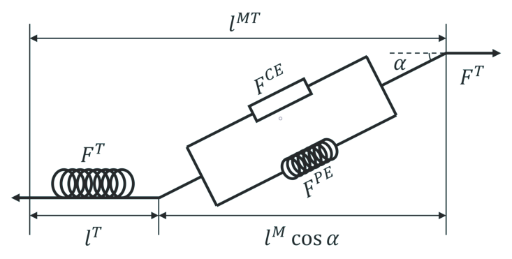
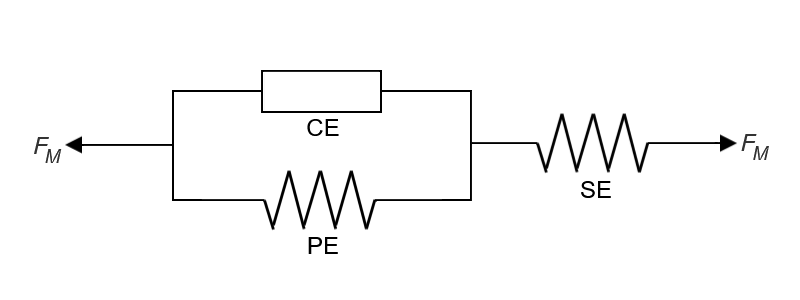
We’ll start by looking at the three-element Hill-type model in Kinesis. This model typically consists of a contractile element (CE) in combination with two nonlinear spring elements: the parallel element (PE), as it is parallel to the CE, and the serial element (SE), as it is in series to both the CE and PE together. Hill-type models often focus on the muscle contraction force, which depends on the muscle’s physical state at a given moment (i.e. CE length and contraction velocity).
|
|---|
| Figure 2 - Three-Element Hill Model in Kinesis |
Relating each element to a biological analogue may be helpful:
- The CE represents muscle fibers that contract when the muscle is activated.
- The PE represents passive connective tissue around the contractile muscle fibers that are elastic and resist stretching or compression. Being passive means that the element does not respond directly to activation.
- The SE represents the tendon (also passive and elastic) that attaches muscle to bone.
A caveat though that these biological interpretations are merely for mental convenience. There are of course much more complex and detailed models of muscle structure and function depending on the characteristics being investigated.
Also, a note if you’re unfamiliar, PE and SE elements are often seen only consisting of a parallel elastic element (PEE) and a serial elastic element (SEE) respectively, but it’s not uncommon to encounter models that also feature a parallel damping element (PDE) and/or a serial damping element (SDE); both the elastic and damping elements are typically considered component parts of their broader respective elements (i.e. the PE consists of the PEE and PDE, and the SE consists of the SEE and SDE).
Overview of the Multi-Segment Hill-Type Muscle Model in Kinesis
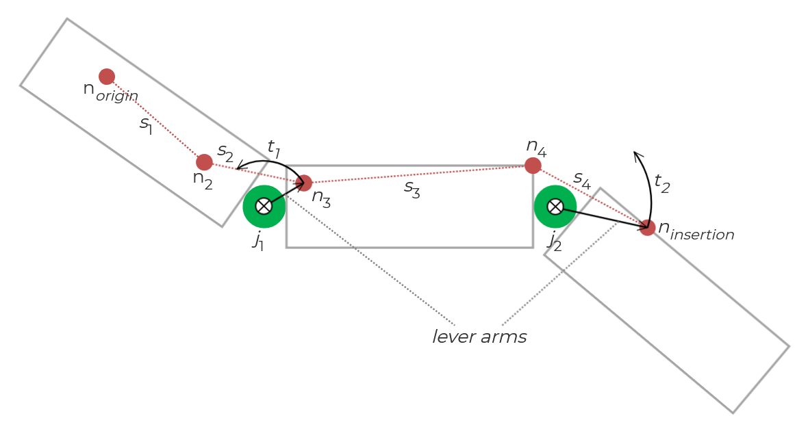
The muscle model in Kinesis is heavily based on the descriptions in (Geijtenbeek, et al., 2013), but its construction was informed by multiple sources and required adjustments to operate smoothly in Unity. In this multi-segment model, the muscle’s physical length is defined by a series of muscle nodes—points defined on the character model—that are linked together to form muscle segments.
Each muscle node has a position defined relative to a body part or “bone” and maintains that relative position to the bone as it moves. Each segment is defined by exactly a pair of nodes, and those with their nodes on separate (but adjacent) bodies/bones are said to span the joint that connects the bodies/bones. These spanning segments are important for calculating the joint torques generated by the muscle.
Each muscle receives an excitation signal, which is then transformed by activation dynamics into a muscle activation, which is what drives muscle contraction. Both the CE length and contraction velocity are used to determine the contractile force being generated, which is then used to calculate the joint torques generated by the muscle.
The joint torques are calculated based on the following. Each muscle’s contractile force (which is a scalar magnitude value) is applied to the line of action, which is a unit vector pointing from the spanning muscle segment’s tail node (the one with the higher index) toward its head node. Put another way, the magnitude of the muscle’s contractile force scales the line of action unit vector. The lever arm is simply the vector from the joint toward the spanning muscle segment’s tail node.
|
|---|
| Figure 3 - Multi-segment muscle model |
Core
This section aims to provide a basic overview of the core muscle model implementation. Please refer to the API documentation (either the version included with the project or online) and the source code for further details.
Concepts
Please refer to the previous Overview of the Multi-Segment Hill-Type Muscle Model in Kinesis section for a conceptual brief.
Directory and File Structure
In the Kinesis/Scripts/Core directory, you should find the scripts that comprise the core implementation of the muscle model:
MuscleNode.cs: Contains theMuscleNodeclass representing muscle nodes.MuscleSegment.cs: Contains theMuscleSegmentclass representing muscle segments.MuscleTendonUnit.cs: Contains theMuscleTendonUnitMonobehaviour class implementing the actual muscle model.
Code Structure
Muscle Node
Muscle nodes are represented by the MuscleNode class. It has a very basic structure:
bone: Represents the “bone” that the muscle node is “attached” to.offset: The relative position (in the bone’s local coordinate space) that the muscle node maintains.
Muscle Segment
Muscle segments are represented by the MuscleSegment class.
prevSegment: References the adjacent muscle segment toward the muscle origin along the muscle path.parentMuscle: References theMuscleTendonUnitthe muscle segment is a part of.head: References theMuscleNodetoward the muscle origin along the muscle path.tail: References theMuscleNodetoward the muscle insertion along the muscle path.joint: If the muscle segment spans a joint, this references the Joint spanned by the muscle segment.jointAnchorBody: References the Rigidbody that is the anchor forjoint.
Muscle Tendon Unit
The MuscleTendonUnit class represents a MTU (muscle-tendon unit, which is the “muscle” we refere to in this documentation) as a whole. It is a fairly large technical class and would take a lot more content to explain in-depth, so here are some of the more important highlights:
-
The public
muscleNodesandmuscleSegmentsfields contain the data representing the muscle path.Caveat: Currently, a Muscle Segment should not be defined such that it would span more than a single joint.
Note: The
MuscleTendonUnitEditorscript listens for muscle node updates and should automatically trigger a rebuild of the muscle segment list. -
The
CalculateJointTorques()andApplyJointTorques()methods are used to iterate the muscle simulation. The functionality was separated between calculation and application to allow for more control and extensibility. Please check out the Muscle Simulation component in the included Demo Scene for an example. -
The
CalculateJointTorques()method takes an excitation signal and a dictionary to store the calculated results. The dictionary uses spanning muscle segments as keys and the joint torques that should be applied as the values. -
The
ApplyJointTorques()static method takes a dictionary in the same form asCalculateJointTorques(). It parses the given dictionary to apply the joint torques to the proper rigid bodies. It is a static method as it does not require any instanced data and receives everything it needs through its arguments. -
There are a number of constants defined in that class. Most of these are part of the more opaque technical details of the muscle model and are not meant to be adjusted casually.
-
normalizedSEESlackLengthcontrols the initial ratio of SEE to CE length out of the total muscle length. -
maxIsometricForcemost directly adjusts the force a muscle is able to generate under contraction. -
activationConstantaffects the activation rate in the activation dynamics.